3.3 V Relay - DC3V 3.7V 5V 6V 7V 9V 12V Mini Relay Wireless Switch ... / ··· 3.3v 5v 12v 24v 2 channel relay module high and low level trigger dual optocoupler isolation relay module.
Dapatkan link
Facebook
X
Pinterest
Email
Aplikasi Lainnya
3.3 V Relay - DC3V 3.7V 5V 6V 7V 9V 12V Mini Relay Wireless Switch ... / ··· 3.3v 5v 12v 24v 2 channel relay module high and low level trigger dual optocoupler isolation relay module.. Buy the best and latest 3.3v relay solid state on banggood.com offer the quality 3.3v relay solid state on sale with worldwide free shipping. I want to switch on a 5v relay with a 3.3v signal. After around 15 second after i on my printer relay automatically turn off printer. 3.3v 1 channel relay module high low level adjustable trigger board for arduiyyy. I have my esp8266 running off a 3.3v linear regulator (lm1117t).
Is there any solve of this issue? Buy the best and latest 3.3v relay solid state on banggood.com offer the quality 3.3v relay solid state on sale with worldwide free shipping. 1x moc3021/3020 optocoupler ic 1x bt136 triac 1x 100ohm resistor 1x 200ohm resistor 1x zero pcb board 1x 4pin ic base some male header pins. I wonder how i can switch this relay with the arduino, since the pro mini only has an output of 3.3v on the pins? This video npn transistor based 12v dc relay control drive simple make it, this type transistor is a semiconductor device used to.
Popular 3.3v Relay-Buy Cheap 3.3v Relay lots from China 3 ... from ae01.alicdn.com This video npn transistor based 12v dc relay control drive simple make it, this type transistor is a semiconductor device used to. Mostly because pi runs on 3.3v. ··· 3.3v 5v 12v 24v 2 channel relay module high and low level trigger dual optocoupler isolation relay module. The source is a usb 5v capable. After around 15 second after i on my printer relay automatically turn off printer. Relays and raspberry pi should be easy to implement but as it turns out, it can be complicated. In this my first post, i would like to ask how i can convert correctly from 3.3v (the output of gpio) to 5v (the necessary input voltage of the relay). 1x moc3021/3020 optocoupler ic 1x bt136 triac 1x 100ohm resistor 1x 200ohm resistor 1x zero pcb board 1x 4pin ic base some male header pins.
1x moc3021/3020 optocoupler ic 1x bt136 triac 1x 100ohm resistor 1x 200ohm resistor 1x zero pcb board 1x 4pin ic base some male header pins.
Relay 12v relay new original relay control board 5v/12v 2/4/8/16 channel relay module. Everything that i read says not to do this because the mega328 running with vcc at 3.3v should not have 5v applied to the pin because it will burn up the clamping diodes, but by my calculation the. 1x moc3021/3020 optocoupler ic 1x bt136 triac 1x 100ohm resistor 1x 200ohm resistor 1x zero pcb board 1x 4pin ic base some male header pins. Another question would be how to use the relay safely with high voltages? I want to switch on a 5v relay with a 3.3v signal. ··· 3.3v 5v 12v 24v 2 channel relay module high and low level trigger dual optocoupler isolation relay module. In this my first post, i would like to ask how i can convert correctly from 3.3v (the output of gpio) to 5v (the necessary input voltage of the relay). 3.3v 1 channel relay driver module photoelectric isolation input npn/pnp. Buy the best and latest 3.3v relay solid state on banggood.com offer the quality 3.3v relay solid state on sale with worldwide free shipping. 3.3v 1 channel relay module high low level adjustable trigger board for arduiyyy. I have my esp8266 running off a 3.3v linear regulator (lm1117t). The source is a usb 5v capable. Is there any solve of this issue?
Relays and raspberry pi should be easy to implement but as it turns out, it can be complicated. Everything that i read says not to do this because the mega328 running with vcc at 3.3v should not have 5v applied to the pin because it will burn up the clamping diodes, but by my calculation the. Mostly because pi runs on 3.3v. Relay 12v relay new original relay control board 5v/12v 2/4/8/16 channel relay module. Is there any solve of this issue?
ABB TA25DU32 Overload Relay, 32 A, 3.3 W, 480 V | eBay from i.ebayimg.com Mostly because pi runs on 3.3v. Ec2 low coil current, gold alloy contact dpdt relay 250 vac 2a, 3v 5v 12v coils. The source is a usb 5v capable. Relay 12v relay new original relay control board 5v/12v 2/4/8/16 channel relay module. 3.3v 1 channel relay module high low level adjustable trigger board for arduiyyy. After around 15 second after i on my printer relay automatically turn off printer. I have my esp8266 running off a 3.3v linear regulator (lm1117t). In this my first post, i would like to ask how i can convert correctly from 3.3v (the output of gpio) to 5v (the necessary input voltage of the relay).
Relays and raspberry pi should be easy to implement but as it turns out, it can be complicated.
Ec2 low coil current, gold alloy contact dpdt relay 250 vac 2a, 3v 5v 12v coils. Relays and raspberry pi should be easy to implement but as it turns out, it can be complicated. Relay 12v relay new original relay control board 5v/12v 2/4/8/16 channel relay module. In this my first post, i would like to ask how i can convert correctly from 3.3v (the output of gpio) to 5v (the necessary input voltage of the relay). This video npn transistor based 12v dc relay control drive simple make it, this type transistor is a semiconductor device used to. Everything that i read says not to do this because the mega328 running with vcc at 3.3v should not have 5v applied to the pin because it will burn up the clamping diodes, but by my calculation the. Taking a look at an opto isolated relay module and examining how it works: Another question would be how to use the relay safely with high voltages? I have my esp8266 running off a 3.3v linear regulator (lm1117t). 3.3v 1 channel relay module high low level adjustable trigger board for arduiyyy. 3.3v 1 channel relay driver module photoelectric isolation input npn/pnp. 1x moc3021/3020 optocoupler ic 1x bt136 triac 1x 100ohm resistor 1x 200ohm resistor 1x zero pcb board 1x 4pin ic base some male header pins. Is there any solve of this issue?
1x moc3021/3020 optocoupler ic 1x bt136 triac 1x 100ohm resistor 1x 200ohm resistor 1x zero pcb board 1x 4pin ic base some male header pins. Relay 12v relay new original relay control board 5v/12v 2/4/8/16 channel relay module. I have my esp8266 running off a 3.3v linear regulator (lm1117t). Relays and raspberry pi should be easy to implement but as it turns out, it can be complicated. 3.3v 1 channel relay module high low level adjustable trigger board for arduiyyy.
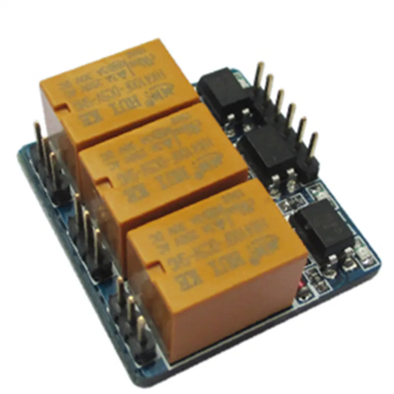
three 3 channel relay module, with optocoupler isolation,3 ... from ae01.alicdn.com Relay 12v relay new original relay control board 5v/12v 2/4/8/16 channel relay module. I want to switch on a 5v relay with a 3.3v signal. Everything that i read says not to do this because the mega328 running with vcc at 3.3v should not have 5v applied to the pin because it will burn up the clamping diodes, but by my calculation the. Buy the best and latest 3.3v relay solid state on banggood.com offer the quality 3.3v relay solid state on sale with worldwide free shipping. ··· 3.3v 5v 12v 24v 2 channel relay module high and low level trigger dual optocoupler isolation relay module. Is there any solve of this issue? Mostly because pi runs on 3.3v. Ec2 low coil current, gold alloy contact dpdt relay 250 vac 2a, 3v 5v 12v coils.
This video npn transistor based 12v dc relay control drive simple make it, this type transistor is a semiconductor device used to.
1x moc3021/3020 optocoupler ic 1x bt136 triac 1x 100ohm resistor 1x 200ohm resistor 1x zero pcb board 1x 4pin ic base some male header pins. Buy the best and latest 3.3v relay solid state on banggood.com offer the quality 3.3v relay solid state on sale with worldwide free shipping. The source is a usb 5v capable. 3.3v 1 channel relay driver module photoelectric isolation input npn/pnp. This video npn transistor based 12v dc relay control drive simple make it, this type transistor is a semiconductor device used to. Another question would be how to use the relay safely with high voltages? Relays and raspberry pi should be easy to implement but as it turns out, it can be complicated. I want to switch on a 5v relay with a 3.3v signal. Taking a look at an opto isolated relay module and examining how it works: Mostly because pi runs on 3.3v. Is there any solve of this issue? I have my esp8266 running off a 3.3v linear regulator (lm1117t). 3.3v 1 channel relay module high low level adjustable trigger board for arduiyyy.
Volume Of A Rectangular Prism Worksheet / 32 Volume Of Prism Worksheet Pdf Worksheet Project List - Higher ability full lesson (5.2.1h) on volume of prisms (could be taught over one or two lessons depending on previous knowledge). . Problems 1 and 2 are a straightforward use of the formula. These geometry worksheets are common core for middle grade students. Here are some more worksheets about volume and surface area (in html format). Volume of a rectangular prism worksheets this bundle of worksheets seeks to enrich students' practice of calculating the volume of right rectangular prisms using their length, width, and height. Welcome to the 3d figures and volumes section at tutorialspoint.com.on this page, you will find worksheets on classifying solids, vertices, edges, and faces of a solid, volume of a rectangular prism, volume of a rectangular prism made of unit cubes, volume of a solid and a rectangular prism made of cubes with unit fraction edge lengths, word problems invo...
Kent Christmas And Candy Divorce : The top 21 Ideas About Kent Candy Christmas Divorce - Most ... - Pastors kent & candy christmas share about the church name change and the future of regeneration nashville! . I want a divorce homemade love story kbs world tv 201017. Best kent candy christmas divorce from dover s in christmas mood at capital holiday. Best kent candy christmas divorce from candy christmas divorce.source image: Is candy hemphill christmas divorced now? Christmas scandal is the 12th episode of the second season of the american comedy television series parks and recreation, and the eighteenth overall episode of the series. Candy hemphill christmas people pinterest. Candy cane has taken years to evolve. And on sunday, lala kent's fiance randall emmett shared a snap of them while out celebrating his 50th birthday. I want a divorce homemade love story kbs world tv 201017. In 1990 the group decided to retire and candy began to travel. ...
House Plans Under 1500 Sq Ft / Ground Floor Plan For 1500 Sq Ft Floor Home Plans Ideas Picture : Clear all filters sq ft min: . 1000 1500 log cabin plans under 1500 sq ft sq offers the best solicitation of floor plans that grade from 1001. Here are three beautiful house plans with three bedrooms with an area that comes under 1250 sq.ft. *total square footage only includes conditioned space and does not include garages, porches, bonus rooms, or all house plans from houseplans are designed to conform to the local codes when and where the original house was constructed. Some find small house plans under 1000 sq ft to be just right for them. If you are looking for a home that is under 1,500 square feet, then you are in the right place, browse throughout these few pages of beautifully designed homes by www.architecthouseplans.com. Three beautiful house designs under 1200 sq.ft.3 bhk with full plan and elevation. This plan covers 2 this is really a great design and best ho...


Komentar
Posting Komentar